Installing Lithium on a sailboat
DISCLAIMER
We do not have a background in electrical installations. If you chose to use some of our material and our processes for your own installation it will be at your own risk. If in doubt - Consult a professional.
This article is part 2 of our LiFePo4 conversion. If you wish to read the first part - click the link below.
Top balancing
When we received the Winston battery cells, they were all pre-charged to 3.3V from the factory. We double-checked all the cells and they all matched the exact same level.
Some might say, we could just connect the cell and create our 12V battery.
But all recommendations from the manufacturer said that the initial top balance of 3.65V would increase the lifespan of the cells.


We initially put all our cells in one row combining the negative together on one side and the positive on the other. Charging the cell from each end of the line-up - But we quickly realized that it would take ages to do the balancing this way.
We split the cell into groups of 4 (putting the cell together as a 12V battery) and then charging to 3.65V in stages.
The first group would be charged to 3.4 - Then rest while the next group was charged to 3.4, followed by the last group. Then do the process again charging to 3.5 and so on until the 3.65V was reached.
All in all the process took a bit over 1 week.
After all the cells had reached 3.65 they were left to rest/set for about 3 weeks before the final assembly where the cells were put in series to make a 12V (13.2V) battery.
BMS Installation and pre-test
The installation of the Overkill Solar BMS was pretty straightforward. Overkill Solar provides a very useful manual for the installation and once the cells are assembled in series it does not take much time to install.
We made a pre-installation of the BMS before installing the battery on the boat - Just to ensure that the battery and BMS worked as intended.
On all cables the ends were de-isolated and a ring terminal was crimped on and secured with heat shrink (with glue inside).


At first, the BMS was not mounted to the battery pack. The pre-test was only to ensure functionality. The Overkill Solar is delivered with a Bluetooth module that easily lets you connect to the App (Xiaoxiang) where monitoring and system changes can be made.
Battery holder and boat installation
As our current battery compartment did not have the size to contain our new batteries, we needed a new solution and a new place to mount the batteries.
In our aft. cabins we have two compartments for batteries. Each compartment is able to contain 2x95Ah batteries. One of the compartments will be used for storage, the second one to hold our starter battery, and the battery for our anchor winch.
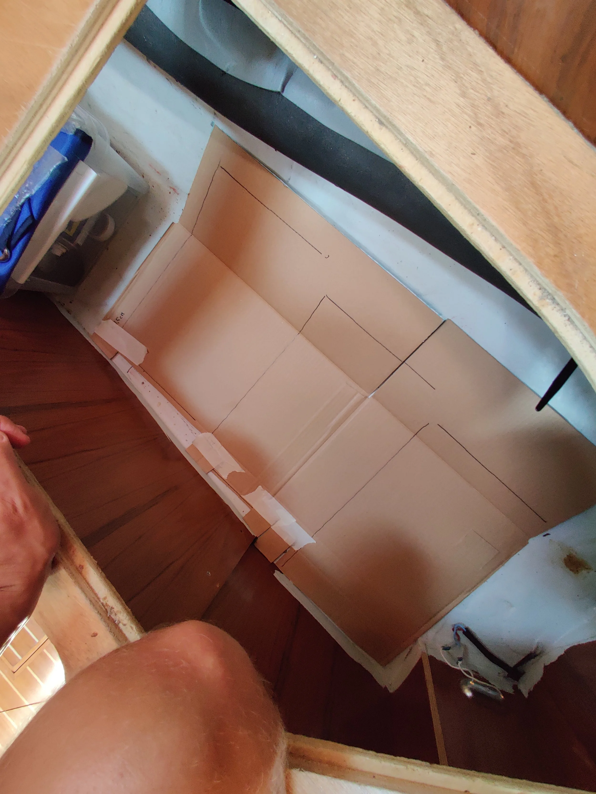
In our saloon, we have plenty of storage space under our sofa/couch. We needed to use this for the new batteries, and with a bit of ‘’templating’’, we built a holder for the battery cells.


Mounting and connecting
We made a test of the batteries in our basement at our house. The test was successful and the batteries performed as intended.
The next step was to mount the batteries in the boat and connect it to the ‘’boat grid’’.
4 cells are mounted together which combined creates a 12V battery. We wanted to optimize the space used for the batteries and therefore the BMS needed to be located as close to the batteries as possible. We have therefore made a temporary solution where the BMS is mounted on top of the batteries.
Later, the BMS will be mounted with a closed case to avoid short-circuit if the BMS moves.
A very critical point for the system was, to be able to remove or add cells if they showed signs of failure. But also to add extra capacity if the 390Ah turns out to be too little.
The battery ‘’pack’’ is secured with a 160A fuse protecting it from a significant current draw.


Schematics of our system
Dealing with our electrical system is a challenging task especially as we have no experience with electric installations - DC or AC.
I have, therefore, throughout the whole process, tried to document and make an updated drawing of our system. It’s an ongoing process and there are certain elements that are not updated yet.
For example, our Solar Panel setup will be made different from the one in the schematic.
The exact changes and precise wiring will be described in a later blog post.
To draw the system, we used Lucidchart.
SY Melody electrical schematic - Click picture for full view